Главная » 2013 Март 30 » Autodesk Inventor Professional 2014 ISZ
Autodesk Inventor Professional 2014 ISZ | 12:08 |
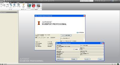
 [/center] [/center] Новый Autodesk Inc. Design and Creation Suites предлагает беспрецедентный доступ к программному обеспечению Autodesk 2014. Портфель охватывает рабочий стол и облака и позволяет проектировать здания, завод, фабрики и дизай; для специалистов и развлеченых сферах в таких как, проектирование, строительство и инфраструктура. Autodesk Inventor 2014 Дата релиза - 26 марта 2013. В последей версии есть много новых и обновленных функций. [spoiler=Inventor 2014 - What's New] Sketch Design Linear and Arched Slots You can sketch linear or arched slots with a single command, similarly as other basic shapes like rectangles or circles. Five new Slot commands are available: - Center to Center Slot command creates a linear slot defined by orientation and length of the slot centerline, and by slot width. - Overall Slot command creates a linear slot defined by slot orientation, length, and width. - Center Point Slot command creates a linear slot defined by the slot center, orientation and length of the slot centerline, and by slot width. - Three Point Arc Slot command creates an arc slot defined by a three-point center arc, and by slot width. - Center Point Arc Slot command creates an arc slot defined by a center point, two-point center arc, and by slot width. Part Self-intersecting sweeps With the enhanced sweep command, you can create sweeps that were previously considered too complex to solve. You can sweep large profiles along small fillets and bends. Non tangent surface path sweeps Previously, creating a swept surface using a profile that was perpendicular to a closed G0 (not smooth or tangent) path failed. New sweep functionality lets you create a surface using a perpendicular profile along a closed G0 path. New Boundary Patch options. Two options are added to Boundary Patch. - Automatic Edge Chain Provides a streamlined workflow when you select multiple edges. You can include edges that are not tangent. - Boundary Patch Create complex shapes using the added weight factors for tangent and smooth boundary patch types. Fillet successIn previous releases, if one edge in a fillet selection set failed, the entire fillet operation failed. In this release, any blend failures open a dialog box with the option to fillet the successful edges. After you fillet the initial edge selection, you can repeat the operation using the same size radius. This action usually blends more edges. Work Point on a sphereIn previous releases, a sphere was not a valid selection to locate a work point. You can now define a work point at the center of a sphere. Derived part color overrideIn previous releases, you were not able to change the color override setting when you placed a derived part. An edit after placing the part was required to remove the color override. In this release, you can keep or discard the source component color override when you place a derived part. Assembly Connect The Connect command is a simple way to position components and describe motion. Creating a connection fully defines the component location and motion in one step. End, mid, and center points are used to associatively position components. The geometry you select determines the default connection type, or you can specify a connection type. The following describes the connection types and how they operate while positioning a component: - Rigid - Removes all degrees of freedom (DOF). Welded and bolted connections are examples of a rigid connection. - Rotational - Specify one rotational DOF. Hinges and rotating levers are examples of a rotational connection. - Slider - Specify one translational DOF. A slide block moving along a track is an example of a slider connection. - Cylindrical - Specify one translational and one rotational DOF. A shaft in a tube is an example of a cylindrical connection. - Planar - Specify two translational and one rotational DOF perpendicular to the linear. To place a component on a planar face, use this connection type. The component can slide or rotate on the plane. - Ball - Specify three rotational DOF. A ball and socket are an example of a ball connection. Note: - With the addition of the connect command, both constraints and connections are now described as relationships. - In the browser, the Constraints folder is renamed to Relationships, and displays in both the Assembly View and the Modeling View. - You can use connections with constraints to position components and describe motion. Lock and Protect For connections that have one or more degrees of freedom, two options are available on the browser context menu: - Lock maintains the current position, but is different from grounding a component. Lock eliminates all motion, but allows the component to change position when related components move. Grounding eliminates all degrees of freedom, and fixes the component position in space. - Protect alerts you if an added relationship violates the required degrees of freedom. Lock and Protect are not available for constraints. Relationship Display Commands Three commands are added to help you manage relationships visually: - Show - To display a glyph that shows the relationship type, select a component. To suppress, unsuppress, or delete a relationship, use the glyph context menu. - Hide All - Remove all relationship glyphs from the display. Hide All does not modify relationships. - Show Sick - Display all relationships that are marked sick. To suppress or delete a relationship, use the glyph context menu. Place Component The first component placed in an assembly is no longer grounded. To ground any component at the origin, use the context menu. The menu contains new options to rotate components in 90-degree increments about the X, Y, or Z axis, before you place them in the assembly. Free Move With the Free Move command, display relationships as an elastic band, and visualize and manage relationships in a new way. Click a relationship icon, and then, to suppress, unsuppress, or delete relationships, use the context menu. Assembly Copy Paste In previous releases of Inventor, a copy and paste operation did not retain component connections or current orientation. The enhanced copy and paste operation produces a duplicate of the copied components with connections and orientation intact. Symmetry Constraints The Symmetry constraint positions two objects symmetrically according to a plane or planar face. The Symmetry constraint is available in the Place Constraint dialog box. Improvements in Angular Constraints When you create an angular constraint, the status bar displays clear instructions to finish the Constrain command. Angular constraints display direction vectors and the angle in the graphics window. The model preview updates when the Angle value changes. Express Mode for Large Assemblies Express mode introduces a new way of working with large assemblies. Large assemblies typically open 4-6x faster, dramatically improving your time to work. Improved Graphics Performance The following graphics enhancements improve the performance of pan, zoom, and rotate of large models in both Full and Express mode. - The following graphics enhancements improve the performance of pan, zoom, and rotate of large models in both Full and Express mode. - The largest objects are drawn first. - The graphics system now uses multiple cores to provide the best possible performance. - A new background operation called consolidation is added. Consolidation draws objects that have the same appearance as a single group, improving the GPU usage. Drawings Split Tables You can split a parts list, hole, revision, or general table, and then relocate the table segments to the desired place on the drawing sheet. Raster Views A new option in the drawing view dialog box creates raster views that do not become precise over time. You control when to make the views precise. Raster views can help you defer the cost of precise drawing view recompute when you edit a large model. For example, open the drawing document and convert all views to raster. Open the assembly file and edit the model. The drawing document displays the changes without waiting for a full recompute. A raster view displays in the browser with a diagonal red line through it. Green brackets frame a raster view in the display. Use the browser context menu to convert an individual view to a precise or raster view. Use the context menu in the display and select Make All Views Precise, or Make All Views Raster to convert multiple views. Appearance Property The model Appearance value is added as a selectable property. You can add the Appearance property to a bill of materials, or a parts list.[/spoiler] The information on .isz - Material for creation of assembly - original (32bit & 64bit) ESD-distribution kits. - The technical improvements relieving the end user from of some problems at installation of the program are lead. - The distribution kit is converted in optimized ISO-image and compressed in ISZ-format. About Autodesk Autodesk helps people imagine, design and create a better world. Everyone—from design professionals, engineers and architects to digital artists, students and hobbyists—uses Autodesk software to unlock their creativity and solve important challenges. [center]  [/center] [/center] Name: Autodesk Inventor Version: 2014 Build 170 Professional Home: www.autodesk.com Interface: english OS: Windows XP / Seven / 8 Size: 5.62 GB [center]Скачать Autodesk Inventor Professional 2014 ISZ[/center] Цитата [center]turbobit.net xlget.com (всегда живая ссылка) unibytes.com gigabase.com share4web.com[/center] | |
| Категория: Программы | Просмотров: 251 | Добавил: gorodoksmol | Теги: | Рейтинг: 0.0/0 | | |
| Всего комментариев: 0 | |


